华南理工大学学报(自然科学版) ›› 2026, Vol. 54 ›› Issue (1): 134-148.doi: 10.12141/j.issn.1000-565X.250053

• 机械工程 • 上一篇    下一篇

基于斜角切削的球头铣刀铣削力建模

靳淇超1,2(), 李军1, 叶子银1, 俞弘宇1, 郭磊3   

  1. 1.长安大学 道路施工技术与装备教育部重点实验室,陕西 西安 710064
    2.中国航发西安航空发动机有限公司,陕西 西安 710021
    3.西安交通大学 精密微纳制造技术全国重点实验室,陕西 西安 710054
  • 收稿日期:2025-03-03 出版日期:2026-01-10 发布日期:2025-06-17
  • 作者简介:靳淇超(1986—),男,博士,高级工程师,主要从事航空难加工材料切削加工表面完整性与抗疲劳制造研究。E-mail: jingqichao@chd.edu.cn
  • 基金资助:
    陕西省自然科学基础研究计划项目(2025JC-YBMS-389)

Modeling of Milling Force for Ball End Milling Cutter Based on Oblique Cutting

JIN Qichao1,2(), LI Jun1, YE Ziyin1, YU Hongyu1, GUO Lei3   

  1. 1.Key Laboratory of Road Construction Technology and Equipment of MOE,Chang’an University,Xi’an 710064,Shaanxi,China
    2.AECC Xi’an Aero-Engine Ltd. ,Xi’an 710021,Shaanxi,China
    3.State Key Laboratory for Manufacturing Systems Engineering,Xi’an Jiaotong University,Xi’an 710054,Shaanxi,China
  • Received:2025-03-03 Online:2026-01-10 Published:2025-06-17
  • Supported by:
    the Natural Science Basic Research Program of Shaanxi Province(2025JC-YBMS-389)

摘要:

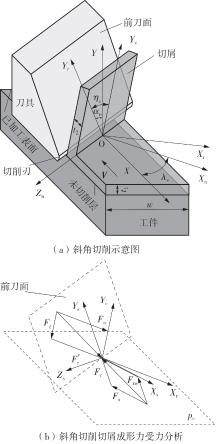
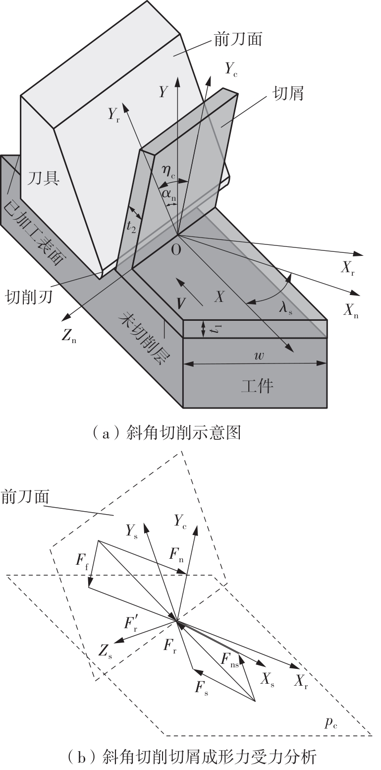
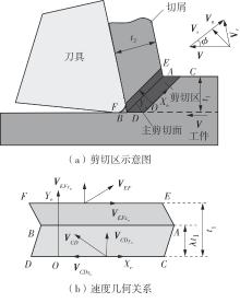
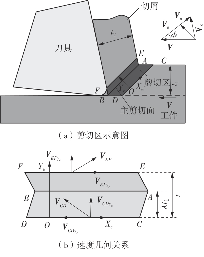
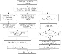
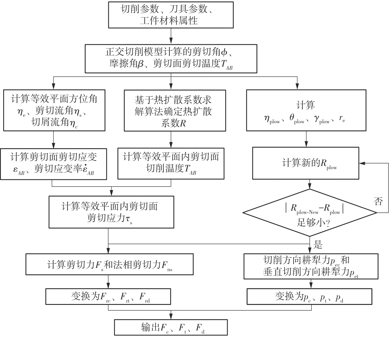
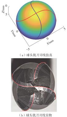
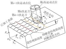
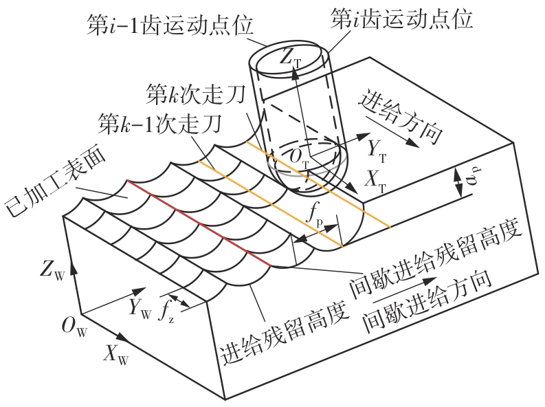
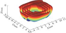
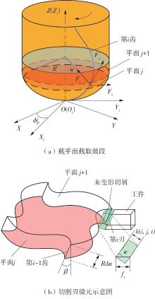
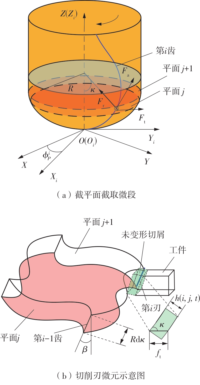
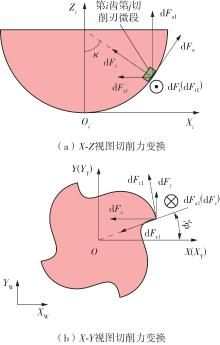
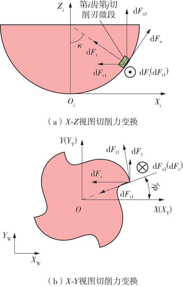
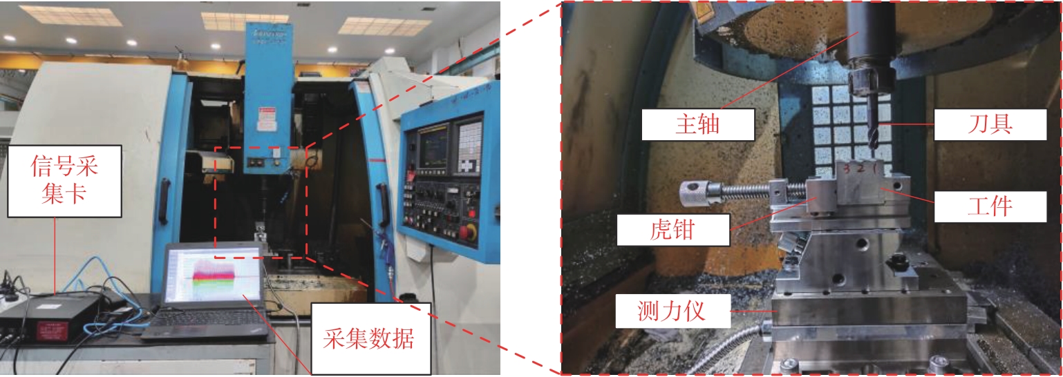
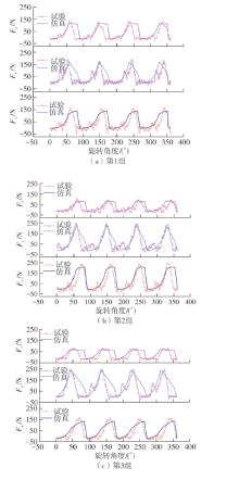
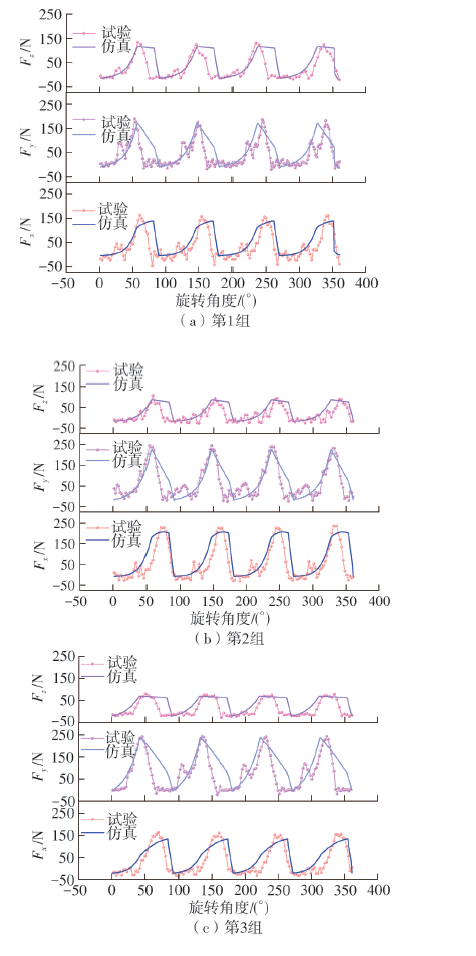
针对球头铣刀在变刃倾角条件下切削时所呈现的三维力场分布复杂、未变形切屑厚度动态变化显著等特点,为实现球头铣刀多轴铣削过程中切削力的高精度建模与预测,提出了一种融合斜角切削理论与动态运动学仿真的铣削力建模方法。基于等效平面法建立斜角切削力学解析框架,通过空间坐标变换将三维切削转化为二维平面切削,推导同时包含剪切效应与耕犁效应的复合力学模型,揭示了刃倾角对切削区材料流动方向、剪切变形区形态以及应力分布的调控机制;其次建立球头铣刀刃线几何特征,结合刀具-工件运动学耦合模型,求解刀齿运动微分方程,并通过改进型Z-MAP算法实现动态加工表面形貌仿真,提取时变未变形切屑厚度分布;进而提出一种多尺度力学映射策略,将刀具刃口沿曲线方向离散为微元切削单元,基于斜角切削解析模型对各微元的切向力、径向力与轴向力进行迭代积分,最终叠加得到完整的三维铣削力时域信号。最后开展实验验证,结果表明:模型在轴向、进给方向与切宽方向的铣削力预测最大误差分别为18.3%、10.8%与22.4%,验证了模型在复杂几何刀具受力分析中的准确性与适用性。该研究方法融合了宏观运动学仿真与微观力学解析,可为球头铣刀的工艺参数优化、刀具结构设计与加工稳定性提升提供理论支撑。

关键词: 斜角切削, 球头铣刀, TANH本构模型, 刀具-工件接触区域, 铣削力模型

Abstract:

In order address the complex three-dimensional force-field distribution and the significant dynamic variation of undeformed chip thickness during cutting with a ball end mill under varying helix-angle conditions, this paper proposed a milling force modeling method that integrated oblique cutting theory with dynamic kinematic simulation, enabling high-accuracy modeling and prediction of cutting forces in multi-axis ball end milling. An analytical framework of oblique cutting mechanics was established based on the equivalent planar method, where three-dimensional cutting was converted into two-dimensional planar cutting through spatial coordinate transformation. A composite mechanical model that simultaneously incorporated both shear and ploughing effects was derived. This model reveals the control mechanism of the tool inclination angle on the material flow direction in the cutting zone, the morphology of the shear deformation zone, and the stress distribution. Subsequently, the geometric characteristics of the cutting-edge profile of the ball end mill were constructed.Combined with the tool-workpiece kinematic coupling model, the differential equations of the tool tooth motion were solved, and dynamic machining surface topography was simulated using an improved Z-MAP algorithm, enabling the extraction of time-varying undeformed chip thickness distribution. Furthermore, a multi-scale mechanical mapping strategy was proposed, where the cutting edge was discretized into micro-cutting units along the curved direction. Based on the analytical oblique-cutting model, iterative integration of tangential, radial, and axial forces for each micro-unit was performed, ultimately superimposing them to obtain complete three-dimensional milling force time-domain signals. Finally, an experiment was carried out for verification, the results indicate that the maximum prediction errors of milling forces in the axial, feed, and width directions are 18.3%, 10.8%, and 22.4%, respectively, verifying the accuracy and applicability of the model in force analysis of complex tool geometries. This research method combined macroscopic kinematic simulation with microscopic mechanical analysis and provided theoretical support for process parameter optimization, tool structure design, and machining stability enhancement of ball end milling.

Key words: oblique cutting, ball end milling cutter, TANH constitutive model, tool-workpiece contact area, milling force model

中图分类号: